Signal processing with 60-GHz Radar: Track motion and azimuth data in real time

11/05/2025 Radar Resources

Detect motion, distance, and angle in real time using the Rutronik System Solutions evaluation kits. The demonstrator visualizes human movement within 10 meters and provides azimuth data via a Windows GUI.

The demonstrator includes the RAB3 radar and RDK2 boards, both of which are developed and provided by Rutronik System Solutions. The demonstrator is designed to detect motion within a 10-meter range in front of the radar sensor (e.g., a person walking). When motion is detected, the sensor delivers the distance and azimuth (angle) of the motion. The demonstrator uses a BGT60TR13C sensor from the Adapter Board RAB3 – Radar and the Base Board RDK2 for the digital signal processing. Since antennas 1 and 3 are used to detect the azimuth, the demonstrator should be mounted horizontally. 

The RDK2 communicates with a Windows GUI via USB and displays the position of the detected motion in real time. The following challenges need to be addressed: 

  • When a person moves between the sensor and a fixed object (e.g., a wall) and then leaves the field of view, the wall is detected as a moving target. This issue can be resolved in the next phase by tracking fixed targets using a low-pass filter.
  • The angle of the detected motion may be inaccurate at greater distances (approx. 10 meters). Filtering the value could be a solution. Using the variation of the phase within a frame as a quality indicator is also a good option.
  • Display the velocity of the detected motion in the GUI. Since the Doppler FFT is computed, the velocity is also known. 

To improve the demonstrator's performance and reliability, we recommend starting the next development phase with a focus on the following: 

  • Implement low-pass filtering to distinguish static from dynamic targets.
  • Enhance angle accuracy through phase variation analysis and value filtering.
  • Integrate velocity visualization into the GUI using existing Doppler FFT data. 

Download the comprehensive Application Note on Signal Processing from Rutronik System Solutions. Whether you are optimizing your own design or are simply curious about advanced radar processing, this resource offers valuable insights. 

FAQ – Radar Processing terms

In reality, we receive multiple reflected signals in response to one transmitted signal because there are other objects around the target. These additional signals are called echoes. 

A returning echo is a delayed version of the transmitted signal. The mixer introduces a frequency difference thanks to the echo signal's time delay. The range can be determined by measuring the frequency of the signal generated by the mixer. 

Three returning signals reach the radar's mixer output. 

The FFT analyzes each returning signal's contribution to the examined signal. It identifies contributions from sinusoids of different frequencies above a certain threshold. 

The amplitudes of the Rx signals for a given range are shown here. Peaks indicate that a signal has been reflected at a certain range. The FFT reveals the mixer output ranges by detecting peak frequencies. This provides the beat frequencies of all three echoes and, thus, the target ranges. 

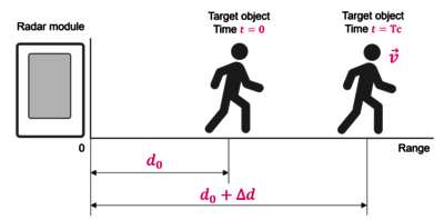
If the target object moves with velocity v, then after a chirp repetition time (T_c), which is the interval between two chirps, the object will have moved a distance Δd. 

This also shifts the phase of the reflected signals. In this case, the amplitude remains practically unchanged. The velocity of a single target can be calculated by observing the phase evolution over time.

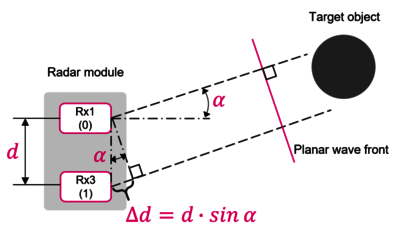
The angle of the target object relative to the radar is calculated using multiple receiving antennas (two in this case).

d is the distance between the antennas. Choose one of the antennas, Rx1, as the reference point (0). Angle α is the "incidence angle" of the planar wavefront coming from the target object. This angle is determined relative to the antennas' imaginary horizontal axis. To reach the second antenna (Rx3), the wave must travel an additional distance (∆d), which is equal to d·sin α and implies a phase difference. This phase difference can be used to compute the angle α. In a case with two antennas, the accuracy may be low due to noise. When using more than four antennas, an angle Fourier transform (FFT) can be applied to extract the phase evolution over time and compute a more accurate angle of arrival. Digital beamforming is used for angle estimation. This method enables a radar transmitter or receiver to focus on a specific direction in three-dimensional space. Left-to-right "scanning" is commonly referred to as azimuth.